Thursday, July 14th, 2005
The Vision Engine supports a number of different texture space effects including bump mapping and specular mapping. In addition to these, it also supports extruded heightmaps. These heightmaps add extra visual detail to the geometry, particularly when viewed at fairly wide angles - where normal bump mapping often breaks down.
As a result of this effect, any shadows cast onto an extruded surface will flow naturally over detailled contours, rather than fall flat along the plane of the underlying geometry. The following video shows this technique in action:
In this video, both the receiver and blocker objects are two triangles each (thus a total of 4 in the scene), and the added detail is provided for the receiver object using the heightmap extrusion technique detailled in this post.
Overview
This affect is achieved by generating an isosurface above the geometry using an extruded heightmap. All lighting, shadowing, and visibility calculations are then calculated purely with respect to this isosurface, and the underlying geometry is modified in order to facilitate this function. Note that this effect is not appropriate in all circumstances, and does exhibit artifacts under certain scenarios.
Process
This effect requires a set of pre-generated texture data:
Color Texture Map
Normal Map
Depth Map
Height Map (optional)
Horizon Map (optional)
The initial render step follows that of traditional shadow mapping - the scene is rendered from the perspective of the light source and the resultant depth map is cached. The final render view is then processed, from the perspective of the viewer, and provided the light source depth map, the color texture map, the normal map, and optional height and horizon maps. The pixel shader for this final stage accomplishes the following tasks:
Determine the initial texel location
Construct a view of a high resolution isosurface
Re-map the texel location based on the view vector
Determine light visibility from our new location
Perform final color texture lookup at the adjusted location
Isosurface Derivation
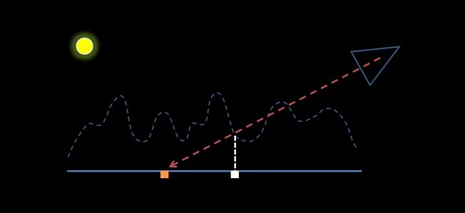
Our initial texel location is determined by a generic texel fetch at the interpolated location. We then must generate an approximation of the isosurface above our geometry as defined by the combination of our bump, height, and horizon maps. We will use this approximation to better ensure that individual fragments are properly visible, in shadow, and textured. The following image shows our isosurface in dotted blue, while our true geometry (minus the view triangle) is represented in solid blue.
There are a number of different ways that we can go about approximating the isosurface - each depending upon the information we have available, and the hardware resources we're willing to consume. The simplest method is to just extrude the normal map, using some pre-determined bias and the normal patch intensity. This will not afford the greatest flexibility to define the isosurface, but it also will not require any additional texture maps. Alternatively, we could define our isosurface using a discrete heightmap that specifies the per-texel distance of the isosurface from the underlying geometry.
Texel Offsets
Once our isosurface is defined, we must offset our current texel location due to the fact that our view vector may intercept the isosurface at a closer point than our initial interpolated coordinate. In our example image above, the view vector (red dotted line) initially intersects the geometry at the orange texel. However, once we've defined our isosurface, we find that the view vector actually intersects the geometry much closer (the intersection point of the red and white dotted lines). Our new texel location, which represents the color data actually visible to the viewer, is found at the white texel location. As a result, we must ensure that we render the white texel data, at the orange coordinate.
At this point we have defined our isosurface, and are aware that we must be willing to offset our texel coordinate in response to the iso-geometry. There are two different ways that Vision derives the required offset: using a parallax map approach, or using a horizon map. The parallax map approach simply defines a relationship between the height (or displacement) of the isosurface from the geometry, and the magnitude of the texel offset vector. Note that the direction of the offset vector will always be equal to that of the planar mapped view vector. Thus, when parallax mapping, a (somewhat) arbitrary offset texel coordinate will be derived that roughly honors the shape of our isosurface. The higher a peak, the greater the magnitude of the offset vector.
Unfortunately, this parallax technique may introduce additional artifacts depending upon the frequency levels of the color texture and the displacement of the isosurface. Thus, Vision also provides support for horizon maps (albeit in a manner that diverges slightly from the normal use of such maps). In this scenario, imagine that a horizon cube-map map is provided where each texel of this map does not define color data, but instead defines a texel offset vector. In this manner, the Vision engine uses the horizon map during rendering in order to determine the correct amount of offset to apply to the initial texel location, using little more than a simple cube-map lookup. This map is generated offline using a custom ray tracing tool.
Shadows
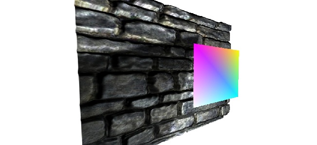
Once we've determined the visible texel location, and the shape of our isosurface, we are able to derive a world space coordinate for this isosurface coordinate. We then use this coordinate to determine light visibility, and apply a shadowing term if necessary. If performance allows, we may also perform additional work here to create a soft shadow effect and add a specular highlight (image below).
Canvas
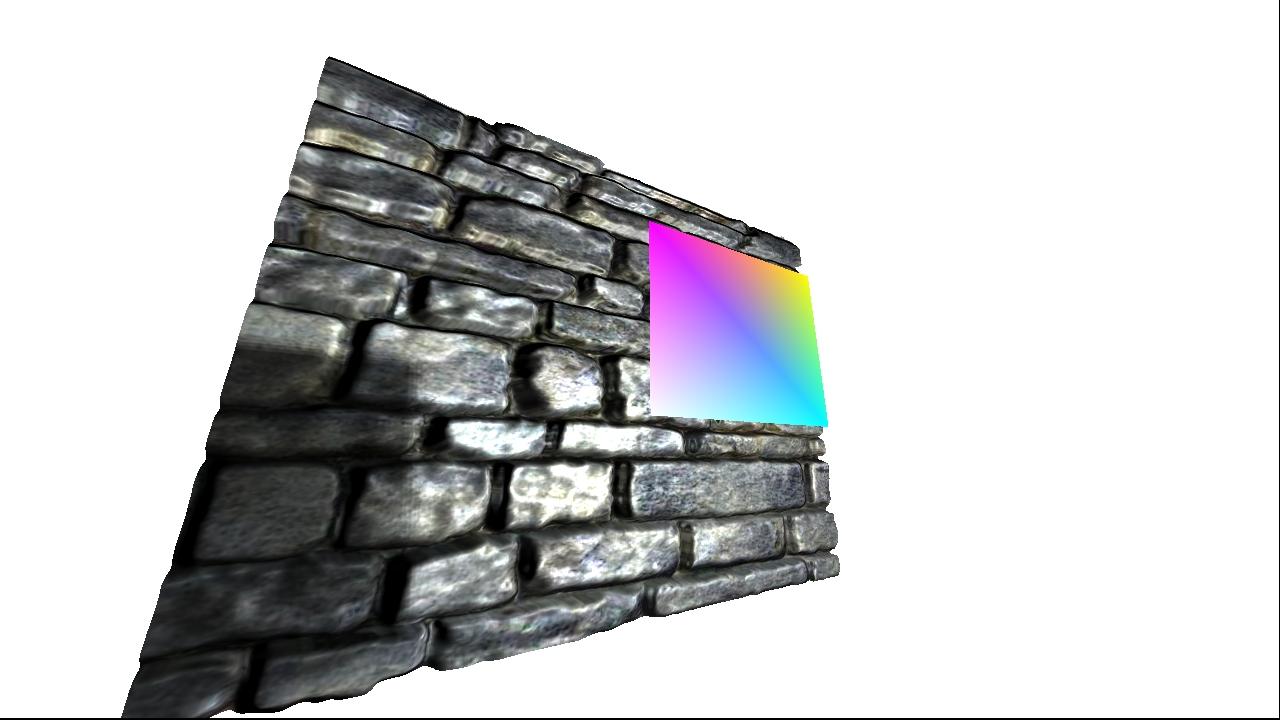
The final step of this effect is to ensure that the displacement effect is maintained, even at wide viewing angles. Note that this effect will break down, similar to bump mapping, when the geometry is viewed from an extremely sharp angle. This effect does not address the underlying shape of the geometry, and it will appear flat in such circumstances. However, we do attempt to improve the viewing angle, above that supported by traditional bump mapping, such that the geometry may still be viewed from relatively sharper angles.
To achieve this effect, we extend the geometry canvas. Imagine if we stretched the solid blue line in our diagram, such that it far exceeded the boundary of the isosurface. By doing this, we ensure that the coordinates of the white texels (those that represent the corrected texel coordinates) will never exceed the original boundary of the geometry - but we specifically do allow the orange coordinates to exceed these boundaries.
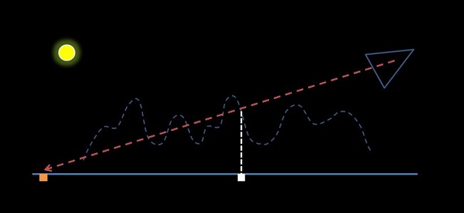
As demonstrated in the image above, there are scenarios where the view vector has intersected the isosurface at a legitimate coordinate, yet the required texel canvas space to render the final result has slipped off the edge of our geometry. By extending the size of the geometry, without extending that of the isosurface, we now have sufficient canvas space to render the surface. In the event that our view vector intersects with our canvas (orange coordinate) without also intersecting our isosurface, we issue a discard instruction in the pixel shader in order to ensure that the fragment does not contribute to the final image.
Thus the final result is a section of simple geometry that (for some scenarios) looks convincingly more realistic than usual.
More Information
For more information on this effect, check out Project Vision, and the Parallax Map Extrusion project page.
